


Part 2: Designing Piezo Handpieces for Ultrasonic Surgery

Ultrasonic handpieces, which include ultrasonic scalpels, phaco handpieces and scalers, use acoustic waves to facilitate the processing of hard or soft tissue. (Credit: Physik Instrumente)
Ultrasonic handpieces are being used with growing frequency in medical applications, for example, with minimally invasive surgical procedures and in dentistry. These instruments, which include ultrasonic scalpels, phaco handpieces, and scalers, use acoustic waves to facilitate the processing of hard or soft tissue. Part 1 of this article, which ran in March 2023, looked at the general structure, design variants, and system design of ultrasonic medical handpieces. Part 2 now reviews driver design, special applications, drive electronics, and failure mechanisms.
DRIVER DESIGN
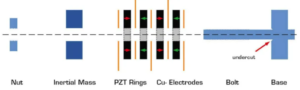
Fig. 1 – Structure of an ultrasonic driver with positioning of the piezo elements on the base body.
In principle, a high-power ultrasonic driver consists of an even number of hard PZT (lead zirconate titanate) rings clamped with a bolt between a base body and an inertial mass (see Figure 1). The resonant frequency and the deflection of the driver are determined by the entire structure and not solely by the properties of the assembled PZT components. The choice of PZT material is mainly determined by the available electronics and cooling. Materials with high coupling, low internal losses and medium bandwidth, e.g. PIC 181, PIC 184, or PIC 144, are usually available (see Table 1).
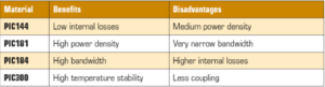
Table 1. Properties of hard PZT.
The electrical contact is established by means of intermediate electrodes made of metal foils. Perforated copper-alloy foils are used to carry the high currents in resonance operation and to dissipate the heat from internal losses. The perforation ensures improved force distribution over the surface while maintaining dimensional stability.
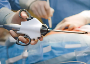
Ultrasonic handpiece for soft tissue dissection and coagulation. (Credit: Physik Instrumente]
Care must be taken to ensure that the correct surfaces to be clamped are as parallel as possible. Angular or tapered surfaces usually lead to immediate failure during assembly. Undercutting the inner edges against which the PZT components rest also helps to avoid possible failure due to tilted surfaces. The flatness and roughness of the surfaces affect the reproducibility of the driver’s properties. The choice of the electrode for the PZT components has a direct impact here since the electrode also forms the mechanical contact surface. The electrical insulation is created using epoxy resins, insulating varnishes or silicone shrink tubing.
The decision as to whether the driver is infiltrated with adhesive (glued stack) or only mechanically preloaded in a dry state (dry stack) depends on the quality of the components used and the area of application. For cost reasons, the glued stack design is often preferred. In this case, the losses due to internal friction are higher and the reproducibility of the operating characteristics lower; however, the structure has a far higher error tolerance than with a dry stack. The adhesive acts as a mechanical mediator for the roughness, flatness and overall mechanical tolerances.
Resonant drivers must always be mechanically preloaded to avoid tensile stresses during the acceleration phases. The minimum required preload results from the maximum acceleration in free resonant operation and the component masses. The aim is to ensure that no tensile stresses occur, and no separation of the components can take place, even at the maximum free deflection. Since the hard PZT components are particularly sensitive to tensile stress, this can lead to destruction of the driver.
A large number of design variables (mechanical, electrical, thermal, etc.) influence the optimal preload, which is why most manufacturers work with fixed preloads that already includes a high safety factor. Typical preloads are 30–75 MPa (megapascal). To ensure reproducible quality, it is necessary to measure this preload when assembling the scaler. This is achieved either by tightening to a specified torque or by measuring the charge generated by the hard PZT rings during assembly. Since this process is highly dependent on the surface qualities and tolerances of all components, the respective properties may vary widely here. To counteract this, the double-tightening method has become established. In this method the driver is short-circuited, fully preloaded, fully unloaded again and preloaded a second time with a fixed torque or up to a defined load. It is also advantageous if the preloaded components are loosely mounted, i.e. to allow possible deviations in parallelism to be compensated for. This can be achieved, for example, by using loose/tolerant screw threading or floating intermediate rings. In this design, however, a polymer sleeve should be fitted on the clamping bolt to prevent damage caused by dropping.
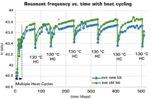
Fig. 2 – Frequency drift in a dental scaler during the initial autoclave cycles. (Source: “Operational performance evaluation of high power Langevin-style transducers for medical applications”, Bromfield, Flitcroft/Moog LLC 2016)
Medical scalers are generally designed for routine sterilization in autoclaves. Depending on the required standard, scalers must typically be hermetically sealed and survive up to 1,000 autoclave cycles (RT<>135°C, 85% relative humidity). To ensure consistent performance despite such severe long-term exposure, the fully assembled scalers are pre-aged in a process known as “burn-in.” During this process the scalers are stressed multiple times in an autoclave at temperatures above their usual operating range, whereby the frequency and capacitance changes that would otherwise occur are anticipated (see Figure 2). It is important to ensure that the completely assembled and preloaded scaler is pre-aged in the short-circuited state. Pre-aging the PZT rings before installation has no demonstrable effect and is not a substitute for pre-aging of the assembled scaler.
SPECIAL APPLICATIONS
A special transducer design is required for use in explosion-proof areas or environments where strong electric fields are not permitted. In such cases the hard PZT rings can be replaced with suitable hard PZT multilayer elements. Although this significantly increases the demands on the power supply and the requirements for active cooling, the operating voltage can be reduced to well below 100 V via this approach.
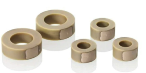
Hard PZT multilayer ring chips for use in ultrasonic handpieces. (Credit: PI)
DRIVE ELECTRONICS
The resonant frequency of power transducers changes depending on the operating status and temperature, whereby the operating frequency and electrical power must be continuously adjusted to ensure optimal operation. The primary task of the drive electronics is to track the resonant frequency of the transducer. In this case, a high-frequency phase-locked loop (PLL) circuit is used to search for the zero crossing of the electrical phase angle and correct the operating frequency accordingly.
When designing the electronics, care must also be taken to ensure that the transducer does not run “dry”, i.e. without a load applied, as this could result in damage to the transducer or even injury to the operator. This is achieved by means of active power control using pulse width modulation (PWM). Modern control electronics for high-power ultrasonic transducers combine both control systems (PLL, PWM) with additional overload protection on a single programmable FPGA (field programmable gate array) chip.
FAILURE MECHANISMS
The most common cause of failure in high-power ultrasonic drivers is breakage of the PZT components. The main reason for this is a loss of preload, which leads to separation and/or cracking of the components. This does not necessarily lead to a loss of functionality, however, in most cases it is clearly recognizable due to an audible buzzing of the scaler. To prevent cracking, the selected mechanical preload when designing the transducer must be high enough that the PZT elements are under compressive stress even in maximum operation. As a first approximation, the preload to be selected is proportional to the mechanical power output.
Article Source: MEDICAL DESIGN BRIEFS