


Prototyping with DIN Rail
If someone were to ask me for the three most important words of advice I could possibly give them when building anything, my answer would be “don’t cut corners.”
Many people fail to follow this advice when prototyping, and everything goes south. One of my favorite (well, least favorite) corner-cutting techniques I would advise not to use is building electronic circuits on perfboards if there is enough of a materials budget for a PCB.
If someone were to ask me for three words of advice on perfboard prototyping or (worse yet) point-to-point soldering, my answer would be “don’t do it.”
However, you may be working on a project with fast-changing requirements and a PCB doesn’t offer enough flexibility to change your circuitry’s topology. Thankfully, there’s one gloriously underrated way to have your prototype cake, and eat it too: DIN rail.
I discovered the joy of prototyping with DIN rail last year during a project with fast-changing requirements. DIN rail offered the flexibility I needed, while also allowing everything to be built in a robust and tidy way.
DIN What?
Before I get into the gory details, I’m sure I’ll need to answer this question for many readers: “What the heck is DIN rail?” DIN stands for Deutsches Institut für Normung (German Institute for Standardization). Based in Berlin, DIN standardizes everything from lighting in hospitals (DIN 5035-3) to paper shredders (DIN 66399). DIN rail is a type of standardized metal rail used for mounting electrical components. Typical examples include relays, industrial control equipment, terminal blocks, and programmable logic controllers (PLCs). You can also buy DIN-rail-mounted power supplies, AC sockets, solid-state relays, and so on. You can buy empty DIN-rail-mounted enclosures to contain a custom PCB. For all intents and purposes, it’s like electrical Lego.
What Are DIN Advantages?
DIN rail-mounted components easily snap on and off the rail. Wiring them up is a case of cutting some wire, stripping, crimping, and wiring. Using relays, terminal blocks, PLCs and whatever other components are going into the assembly, you can quickly wire and test as fast as building the same thing on a breadboard. Except with DIN, you can build in a way robust enough to go into a device.
Did your requirements change? Did you discover a bug? You can modify the DIN rail assembly just as easily as you built it. And you won’t leave messy scars you’d likely produce when modifying a perfboard or a custom PCB.
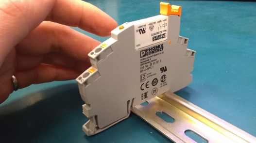
Mounting Components with DIN Rail
Components intended to be mounted to DIN rail have an easily identifiable clip at the bottom that simply snaps onto the rail.
Use screws and locknuts. You can also buy enclosures designed for use with DIN.
Connecting Things with DIN Rail
Terminal blocks can be used to distribute power and split a signal that needs to connect to multiple components. In both cases, I recommend terminating wires with ferrules. This avoids dealing with fraying strands of wire when wiring things up. Trust me, it would be difficult to use flying leads with stranded wire, and solid-core is too annoying. I usually use American Electrical ferrules and this crimp tool, which hasn’t steered me wrong yet.
For screw terminals, I also recommend ferrules or spade crimps—depending on the type of screw terminal. If possible, get double-crimped crimps. These have one crimpy bit that grabs the bare wire and provides a mechanical and electrical connection. They have a second crimpy bit that grabs the jacket of the wire and provides a second, redundant mechanical connection. These have the obvious advantage that they can much more safely be used in AC and any higher current or higher voltage applications. They are also much less susceptible to the strain (and eventual fraying or breaking) that often results from wires being moved around, disconnected, and reconnected. This happens a lot while debugging a prototype.
Cable Management When Working with DIN Rail
Raceways are your friend. (I’m not talking about places where you race your car.) I’m talking about cable raceways, which are also called wire ducts. When building an electrical assembly by hand, raceways are great for hiding excess wire that may be a little longer than it should to be pretty. Good old-fashioned cable ties are indispensable for bundling together wires that deserve to be bundled.
Adhesive cable tie mounts can be useful for proof-of-concept prototypes, but I don’t encourage their use for anything needing to last. Eventually they lose their stick and fall off. Screw-on cable tie mounts are a better choice (for example, these).
I recommend labeling everything. One way to label wires and cable is using ID cable ties—though they sometimes have the disadvantage of catching onto things easily. Another alternative is to attach a label printed with an ordinary label maker to your wire or cable and put clear heat shrink over top to ensure it stays.
Limitations
I don’t recommend building custom high-frequency circuitry with DIN rail. In most situations, you’ll still want to design a custom PCB. It will likely be more cost-effective to use custom PCBs for production parts, as a DIN rail assembly will need to be built by hand. Custom PCBs can be built in a largely automated way. Don’t forget that a DIN rail assembly will need to be documented and this documentation must be kept up-to-date with the assembly.
DIN rail assemblies can be a great option for one-off prototypes where changing requirements are expected.
Aricle source: Medical Product Sourcing