


6 Ways Surgical Hand Tool Size Can Be Reduced. Will Performance Suffer?
Surgical hand tools continually add advanced capabilities that also drive the need for more power and larger motors. However, adding weight and bulk to the instrument can reduce surgical precision and increase operator fatigue. One popular option — brushless DC motors (BLDC) — can provide designers the high-power density and high reliability they need when adding functionality to their tools. With a good balance of tradeoffs and other design factors, designers can reduce slotted or slotless BLDC motor sizes and meet the application’s performance requirements.
Mechanical power is the product of torque and speed. All else being equal, the torque generated by a motor is roughly proportional to its volume. Torque is created by the presence of current-carrying wires within a magnetic field, and it can be increased by simply adding more wires or more magnets. However, this brute force tactic alone will inevitably lead to increased size. Fortunately, more sophisticated motor design methods can increase power output for smaller packages.
Method 1: Optimize the Winding To Supply Voltage in Surgical Tools
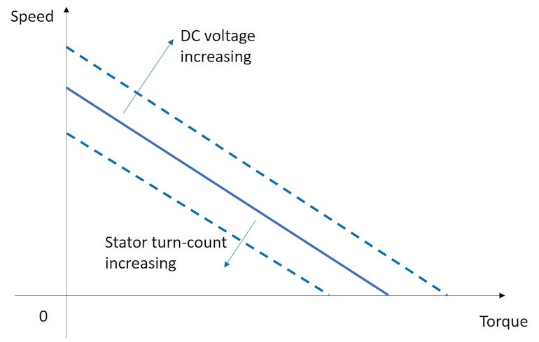
When more voltage is available for the motor, the faster it can turn at any given torque and, therefore, more power is produced (Figure 2.) This allows a smaller motor to be used to achieve the same output power. However, higher voltages generally dictate larger batteries that can negate the benefit at the tool level. Designers of battery-powered tools often must choose from a limited variety of available battery cells and connect them in series to achieve the desired voltage. Obviously, this requires a whole number of cells and a discontinuous set of possible voltages. Therefore, even a small boost in voltage to increase motor power could require adding another cell and its associated size and weight. A good motor design partner can tweak the diameter of the wire in the motor and the number of times the wire wraps around the stator, or turn count, to maximize the power at convenient battery voltages. (All Image Source: Portescap)
Method 2: Material Choices
While power can be increased simply by including a higher volume of magnetic material, designers can also upgrade the magnetic material so that it can generate more magnetic flux for the same size and weight. High power density motors typically use magnets made of neodymium, which is one of the highest-grade magnetic materials available. The material of the wire used to construct the coils is also important. Lamination material also impacts power. High-grade lamination steel provides a more efficient path for the magnetic flux to travel, which amplifies the contribution of the magnet material. Ultimately, any material choice that reduces friction, such as in the bearings and gear teeth, will minimize the losses during the conversion from electrical to mechanical power and get more out of a sleeker design.
Method 3: Precision Manufacturing
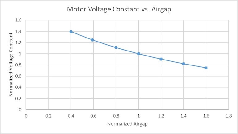
Obviously, tightly arranged motor components will make the overall package smaller. But, positioning the magnets and coil as closely together as possible also increases power. Minimizing the distance between the magnet and the coil — known as the airgap — strongly increases the airgap’s magnetic field strength and, therefore, the motor voltage constant and the motor’s overall performance (Figure 3.) However, decreasing this distance is easier said than done because it also requires very tight tolerances to avoid the rotor and stator rubbing together during operation. A precision motor supplier can handle the machining and workmanship required to perform this task.
For slotted BLDC motors, precision assembly methods can also add to the amount of copper that can fit into the slots of the stator. By carefully selecting the wire diameter and shape of the slot, you can maximize the slot fill factor and deliver the most power out of the smallest space.
Method 4: Manage Temperature Rise
Temperature rise is an extremely important aspect of motor sizing. A very tightly configured motor will naturally get hotter than one with its heat-generating elements spaced farther apart. This problem can worsen if the voltage and current are increased to meet power requirements. To offset this effect, certain materials can be chosen for the motor housing in order to conduct heat away from the motor coils, which can otherwise become so hot during operation that the insulation melts and creates an electrical short. Extreme heat can even decrease the strength of permanent magnets. Additional heat sinking on the outside of the motor or air or liquid cooling may be needed to dissipate heat, which will also affect the overall size of the tool.
The following formula can be used to calculate the motor winding temperature to determine whether the temperature rise will cause the motor to fail prematurely. A talented motor supply partner can help determine the value of the constants for each unique application. Note that this theoretical calculation can help guide prototype selection, but only testing in the application can confirm whether the motor is operating near the limits.
Tcoil = Rth x R0 x (1 + a (Tcoil – Tamb)) x I2 + Tamb
Motor thermal resistance: Rth (°C/W)
Terminal resistance at room temperature: R0 (Ω)
Temperature coefficient of resistance for copper: α (/°C)
Ambient Temperature (immediately surrounding the motor housing): Tamb (°C)
Method 5: Using Gear Reductions
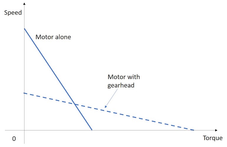
Brushless DC motors run most efficiently at relatively high speed, but many surgical tools need to operate much slower. In these cases, a gear head is often used to allow the motor to run at an efficient speed while increasing its torque output. While this allows a smaller motor to do the job, the gearing itself takes up space because its axial alignment with the motor adds length. The decision to use a long but sleek gear motor or a shorter but larger diameter motor depends on the required layout of the tool. One way to minimize the extra length of a gearhead is to keep the gear ratio low enough so it can be handled with only one stage of gearing instead of multiple stages stacked on top of each other. Planetary gearheads are generally able to create higher gear ratios in a smaller space than spur gearheads.
Method 6: Motor Integration
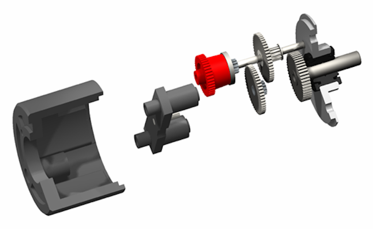
The best way to minimize surgical tool size may not only be to shrink the size of the individual components but to optimize the way the individual components fit together. A motor is traditionally built within a metal housing that encapsulates the components so it can be shipped in one piece and inserted into the hand tool. The motor housing is often immediately surrounded by the outer casing of the hand tool. Both components perform important functions, but these functions can often be accomplished with one combined component. A motor supplier experienced in hand tool design can either provide a motor with a housing that can double as the outside of the hand tool or can coordinate with the tool manufacturer to create a frameless design with the motor built directly into the tool’s outer casing. Similarly, other components such as tool drivers, seals, electrical connectors, and mounting hardware can be designed directly into the motor to eliminate redundancies and save space. Finally, selecting a sensorless motor can save space since Hall sensors can add a few millimeters to the motor length. However, sensorless motors require more complex controls whose larger boards can offset any space gains.
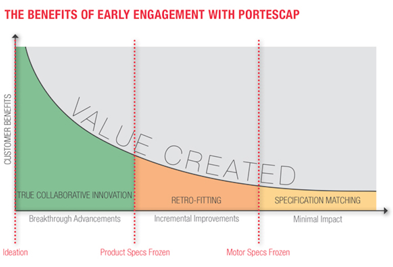
Partner With an Expert Motor Supplier Early
Creating high power density motors involves sophisticated design tactics, high-quality materials, precision workmanship, and knowledge of how the motor fits into the greater architecture of the tool. A motor supplier that is knowledgeable about all these aspects can make the best design choices for a sleek and powerful hand tool. This supplier can achieve the most success by incorporating these design methods early. For best results, include an experienced motor partner at the concept or even the ideation phase of the tool’s development.
Article source: MDDI Online by William Huang