There’s strong demand for smart, new lifesaving and life-enhancing technologies in the global medical device market. To meet this demand, medical device manufacturers are looking for ways to drive growth through innovation. With medical device sales expected to climb to nearly $658 billion (USD) by 2028, finding innovative materials to propel business forward and create a competitive advantage will become even more important in the future.
Yet, medical device designers and manufacturers face an onslaught of challenges. Labor shortages, rising materials costs, and ongoing supply chain disruptions are leading to delays in both engineering and manufacturing processes. To meet this moment, the medical device industry needs innovative solutions — or their go-to-market plans could be seriously threatened.
On the materials science side of the industry, innovation is already here. When it comes to medical device components, rarely does an off-the-shelf material make the grade, as this is not a one-size-fits-most industry. More often than not, medical device engineers and manufacturers want a specific performance attribute for their component, which usually requires flexible, customized silicone and polymer solutions.
Medical device manufacturers typically turn to materials scientists when they have a silicone or polymer material that works well enough but doesn’t have all of the attributes they would like to take the product to the next level. Another reason material scientists are engaged is because the manufacturers have heard complaints from their customers, and they need to resolve a specific problem. Silicone and polymer innovation has come a long way in recent years, and there are several new or alternative materials that can deliver improvements and drive innovation forward.
ENTER THE ELECTRICALLY CONDUCTIVE ELASTOMER
Traditionally, medical device components that require electrification to function use silver alloy as the material of choice. However, silver alloy can be costly, driving up the total cost of a medical device. A more cost-effective, high-performing alternative is electrically conductive elastomers — either silicone or other organic rubber. Electrically conductive elastomers can improve conductivity and overcome many of the same problems resolved by silver alloy.
There are a number of medical device component applications for flexible conductive silicone and nonsilicone materials that can be served without the need for silver alloy. For example, an ethylene propylene diene monomer (EPDM) elastomer was recently used to develop a conductive component in a bathroom scale. The elastomer was bonded to the stainless-steel insert of the scale, and through electrical conductivity, the device measures heart electrical signals through the bare feet of the person standing on the scale.
POLYISOPRENE: AN OLD MATERIAL GETS NEW LIFE
Polyisoprene material has been around for a very long time. However, interesting applications are emerging for polyisoprene materials in medical device component manufacturing. Polyisoprenes are polymers that are produced by the polymerization of isoprene, and they are more commonly known as natural rubber. Polyisoprene material has recently been successfully used to develop surgical trocars, meeting the high requirements for mechanical durability, puncture resistance, and coefficients of friction. This particular trocar application used synthetic poly-isoprene made from petrochemicals, rather than natural rubber extracted from trees. This is the same rugged material used in vehicle tires.
When molded into medical device components, synthetic polyisoprene material can withstand the rigors that surgical instruments are put through daily. The material won’t rupture or tear, giving surgical staff a high-performing and reliable surgical trocar. Specific custom compounds of synthetic polyisoprene materials are also biocompatible for certain medical device applications.
EXPLORING NEW MATERIALS SCIENCE TECHNOLOGIES
Materials science experts aren’t just finding new possibilities for novel materials. They have been advancing new technologies such as halogenated butyls for medical device component development. Halogenated butyls are clean and have unique properties such as being remarkably impermeable. They can prevent the passing of gasses and water vapors through the membrane, holding a pressure of CO2 gas or other gas behind a bromobutyl or chlorobutyl rubber.
Another material that innovative engineers use in medical device components is an FKM fluoroelastomer, otherwise known as fluorocarbon elastomer. A synthetic rubber material, FKM fluoroelastomer is typically used in seals and barrier layers because it can withstand harsh environments. Due to its ruggedness, the vast majority of fluoroelastomer material is used in automotive applications such as powertrain and fuel systems. However, fluoroelastomers also have great potential for oncology drug devices that have aggressive chemicals and use-cases. Recent improvements to fluoroelastomers have led to better mechanical resistance and medical device component materials that are impermeable to gasses and vapors.
AN ALTERNATIVE TO LIQUID SILICONE RUBBER (LSR)
Many medical device designers and manufacturers have long specified LSR, primarily because of the material’s familiarity. It aligns with most regulatory requirements and performs predictably on the manufacturing line and in the field. It’s also inherently inert and biocompatible — two attributes that are critically important for medical applications.
However, with supply chain uncertainty and greater pressure to reduce costs and get products to market quicker, pressures with LSR material availability have constrained the market. Mature organizations that have broad material experience and capabilities can reexamine both the design and material options with medical device engineers, saving time and money rather than being limited to one material option.
CONSIDER CUSTOM BLACK RUBBER
Custom black rubber is not a new material but has emerged as a viable material alternative. With supply chain uncertainty, some medical device engineering teams have been exploring alternative materials such as custom black rubber and engaging materials science providers earlier in the design process. This has led to the discovery of critical-to-function components that deliver superior results in trials, on the manufacturing floor, and in the field.
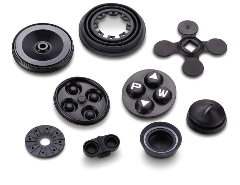
Custom black rubber has many similarities to a medical-device manufacturing favorite, LSR, and is ideal to have in the materials mix for medical device component development. Custom black rubber has excellent electrical insulation, good cold temperature flexibility (to -50 °C/ -58 °F), high temperature tolerance, chemical resistance, and strong compression characteristics. It also provides a clean surface finish, flame retardance, biocompatibility, non-black color options, and compliance with major regulatory organizations.
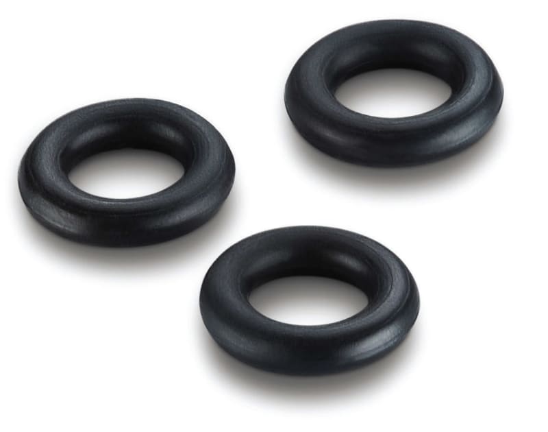
Custom black rubber is ideal for medical devices. While the primary challenge in medical devices is sealing against harsh chemicals and fluid, custom black rubber offers excellent resistance to polar fluids, polar solvents, alkaline-based cleaners, and steam/hot water. It’s also highly durable, providing outstanding abrasion resistance — which is critical for mitigating tears and leaks. Components made with custom black rubber are specifically designed to withstand aging, ozone, and UV rays.
When it comes to temperature resistance, custom black rubber withstands extreme high and low temperatures. It offers temperature stability from -55 °C/ – 67 °F to 150 °C/302 °F. It is also extremely flexible, allowing for 600 percent elongation and a tensile range of 500-3000 psi to ensure that rubber seals can move and avoid creating leak paths. The material allows many opportunities to innovate because the compounds have multiple ingredients that make the number of formulations almost endless.
A NEW ERA OF INNOVATION
New and alternative materials for medical device components show great promise for this next era of innovation. They can be completely customized for old and new applications alike. Medical device engineers no longer need to stick with their standard materials, especially when their objective is industry-leading innovation. Materials flexibility, with the help of materials science expertise, will help deliver these new products to market, fast.

While the word custom might convey a slower development process, innovation in materials science can happen at a rapid pace. Experienced elastomer specialists can get a head start by accessing years of intellectual property to customize a material, starting from something previously created for a similar application within a vast library of customer material compounds. Because of this, companies that are creating custom materials designed for purpose, are getting a leg up on their competition. They are discovering that they can design better products at a faster pace — while minimizing costs — with new and alternative silicones and polymers.
The key to rapid innovation is to collaborate with materials science providers early in the design process and bring a wide cross section of experts to the table — materials scientists, design engineers, and tooling experts. By engaging early, the right questions will be asked up front, which in turn, equips designers with the right design criteria to ensure that components are developed for production success. Medical device engineers should look for materials science providers that can produce production-intent prototypes, allowing them to test fully functional parts of critical-to-function components early in the innovation process that are ready to be manufactured at scale.

With demand for medical devices projected to skyrocket in the next five-plus years, the world demands medical device manufacturers’ best. A growing senior population, consequences from the global pandemic, and climbing mortality rates for heart disease, cancer, obesity, and other conditions are all contributing to a strong and sustained market demand for medical devices. Being open to new and alternative materials, and enlisting the resources and expertise of materials scientists, can help medical device engineers deliver on their toughest projects.
This article was written by Don Bonitati, Director, Global Medical Market, Minnesota Rubber & Plastics, Minneapolis, MN.
