Injection molding design fundamentals: Snap-fits for plastic parts
One of the greatest disadvantages of plastic materials is their flexibility and relatively low stiffness. One of the greatest advantages of plastic materials is their flexibility and low stiffness. Your perception of which of these statements is true depends on how you, as a designer, optimize the inherent properties of plastic materials. I personally prefer the latter statement, especially when I am designing products to be aesthetically appealing and easily assembled with minimal hardware.
At one time, all products required hundreds of screws to be assembled, which demanded extensive amounts of labor and parts. The aesthetics of the final design were often compromised by numerous exposed screws and fasteners. Today’s industrial designers don’t want exposed fasteners compromising the aesthetics of their product designs, and manufacturing engineers are being pressured to produce high-quality goods more efficiently. The solution to this apparent paradox is utilizing snap fits as a means of assembling parts that is ideally suited for plastic materials. The remainder of this article will be dedicated to discussing all the considerations associated with properly designing snap fits.
Before I discuss the types of snap fit designs and their associated design parameters, I’d like to focus on some basic functional requirements for snap locks, which are listed below.
• A snap lock must be designed to work within the strength limits of the plastic.
• A snap lock can be designed for single one-time use.
• A snap lock can be designed for repeated use.
• A repeatedly used snap lock should be designed to limit the deflection within working stress levels. Ideally, a snap lock should only interlock two parts by constraining them in a single axis.
• A snap lock can be designed for on/off bidirectional applications.
• A snap lock ideally should be engaged with little to no residual stress.
• A snap lock can be designed to apply a constant residual force.
• A snap lock should be designed to account for tool design.
• A snap lock should be designed to compensate for tolerances.
• A snap lock should be designed to withstand opposing separation forces.
Although there are three basic types of snap locks—annular, cantilever and torsional—they all share the design considerations listed above.
Annular snap lock
The distinguishing attribute of an annular snap lock is the attachment of the protruding locking feature to a contiguous wall or edge that must deform to enable the locking protrusion to snap over the mating locking feature. In my opinion, these snap locks are the most difficult to design, prototype and optimize because the forces applied to deform and snap two parts together are very difficult to calculate or predict. Annular snap locks are often seen in snap-on bottle caps, pen caps, plastic containers and low-cost consumer electronic housings. The performance of an annular snap lock is highly dependent on the materials of both mating parts, the wall thicknesses and the amount of interference. Other critical considerations include part size and geometry, molding tolerances, flatness and location on a surface.
Torsional snap lock
Torsional snap locks are ideally suited for any application requiring a radial lock, such as a ratchet lock, threaded-bottle-cap safety lock or push-release lock. Designing a torsional snap lock is much less complicated to predict than an annular lock but more difficult than a simple cantilever snap. The stressed torsional portion of the lock must be designed to flex within the elastic working stress of the material while inducing enough forces to perform its desired function. Finger pressures to engage or disengage the snap should also be comfortable for the average person. These pressures will be a function of surface area of the release button and the force required to deflect the snap. In addition, the snap must be designed for ease of molding, tolerances, material properties and product life.
Cantilever snap lock
Cantilever snap locks are the most commonly specified snap locks and the easiest to design. They are based on a simple beam, which is designed to deflect a specified amount based on the height of the snap hook. The snap-hook profile is typically designed with a profile of a right triangle with a tapered leading edge, an equilateral triangle or a half-round configuration. A right-angle profile will provide a very secure interlock that can only be disassembled under normal conditions by manually releasing the snap. The equilateral and half-round profiles enable snapping on or off two parts simply by pressing them together or pulling them apart. We will examine the design considerations associated with each of these snap options based on the previous list of parameters.
Deflect within the strength limits of the plastic
All snap locks are based on the same principles of temporally deforming materials with interlocking features such as hooks and mating detents, which can interlock by returning to their original unstressed state. All snap locks must be designed to restrict material deflections within the strength limits of a material’s tensile strength to avoid permanent deformation. Snap locks designed for single use or fewer than five repeated flexures could be designed with stresses up to the material’s elastic limit. However, induced stresses in snap locks intended for repeated use should not exceed the material’s maximum working stress level, which is typically about 50% of its elastic limit. It should also be noted that the mechanical properties of plastics vary greatly with temperature. Therefore, the elastic limit and maximum allowable constant working stress should be based on thermal conditions.
Calculations for determining the force required to flex a snap feature are based on the following parameters:
• Material elastic modulus, maximum strain and stress within its elastic region;
• geometry of the material to be flexed; and
• amount of deflection determined by the height of the hook profile or the force required to deflect the snap lock.
The forces, stresses and maximum allowable deflections for the three types of snaps can be estimated based on equations or more accurately determined using finite element analysis (FEA). The complexity of the calculations depends upon the part geometry, assumptions, materials and type of snap lock.
Annular snap
Annular snap calculations are frequently based on only one material flexing while the other is fixed. If both parts are assumed to flex, the deflections are reduced by 50%, which assumes both materials are identical and have the same wall thickness. Friction is also ignored. The most common formula for an annular snap is limited to cylindrical shapes with one member represented as a solid part pressed into another flexible part. Calculating strain is relatively easy, as shown below:

The strain must remain below the maximum allowable within the material’s linear stress-strain curve at a specific working temperature. However, insertion force calculations are a bit more complicated since they require a geometric factor X, which represents the geometric rigidity of the two mating parts. Basic insertion force is calculated using the equation below:
F=y•d•Es•X
F = insertion force (lbs or newtons)
Y = undercut (in. or mm)
d = diameter of the cylinder or joint (in. or mm)
Es = secant modulus (psi or MPa)
X = geometric factor
All of the variables above are easy to define except X, the geometric factor, which is geometry specific. The formula below is used to calculate X for the annular geometry of a rigid shaft and flexible out ring. It has been provided for reference.
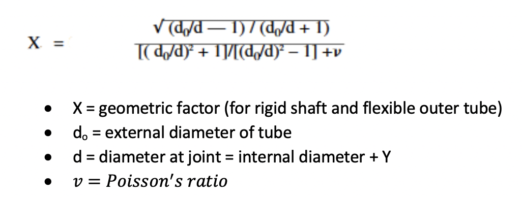
If the outer tube is rigid and the inner shaft is elastic, the formula is identical to the one above except v, Poisson’s ratio, has a negative value vs. plus as shown above.
These calculations are adequate for simple cylindrical shapes but are not applicable to more-complex shapes, such as electronic housings, food containers, toys and hundreds more. In these instances, FEA must be used to accurately predict the insertion forces, allowable deflections and maximum retention force.
An FEA example of an annular snap applied to a small injection molded box is shown below:
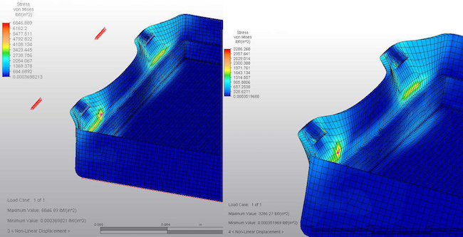
The detail of the 0.03-in. snap feature is shown in the FEA images above. The box at the left is modeled in polycarbonate and the one at the right is polyethylene. The distortion in these images has been greatly exaggerated to illustrate the type of deformation that occurs as the snap is flexed. The maximum stresses in each analysis differ by 100% due to the much higher modulus of polycarbonate. In either case, the 0.03-in. undercut proves to be excessive, inducing stresses well beyond the elastic limits of either material. These types of calculations would be much too time consuming and complicated without the aid of FEA.
Torsion snap
Torsion snap features are ideally suited for applications requiring repeated assembly and disassembly, such as a push-button quick release locking two covers or parts together. It is based on a simple principle of a twisted beam, as shown in the illustration below. The angle of twist, length of the beam and modulus of material will affect the torsion of the snap. The same parameters stated for snap locks also apply for the torsion snap. The maximum twist is limited by the maximum allowable shear stress within the material’s elastic limit, as shown below:

The angle of twist for the torsion latch based on the applied force (F) is shown below:
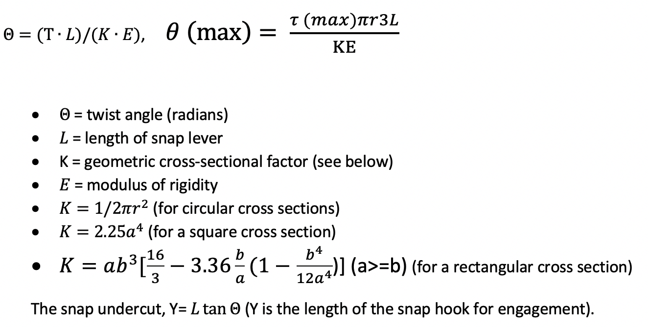
These equations are provided in Roark’s Formulas for Stress and Strain, which is typically found in most mechanical engineers’ libraries. It should be noted that these calculations are based on materials with a linear stress-strain curve that lies in the elastic limits of engineering materials. Most commodity plastics, such as polypropylene, polyethylene or high elastic materials, do not have a linear region in their stress-strain curves where these equations will not accurately predict their behavior. In such cases, a non-linear FEA analysis must be used.
Cantilever snaps
Cantilever snaps are by far the most commonly applied snap locks because they are best suited for most applications. They are also the easiest to design, mold and predict. There are a variety of cantilevered snap-fit designs, which are all based on the same principle of a simple beam. The parameters previously cited for the other snap fit designs also apply for cantilevered beam snap fits. The basic formula for a simple deflecting beam, which is provided in Roark’s book, is shown below:
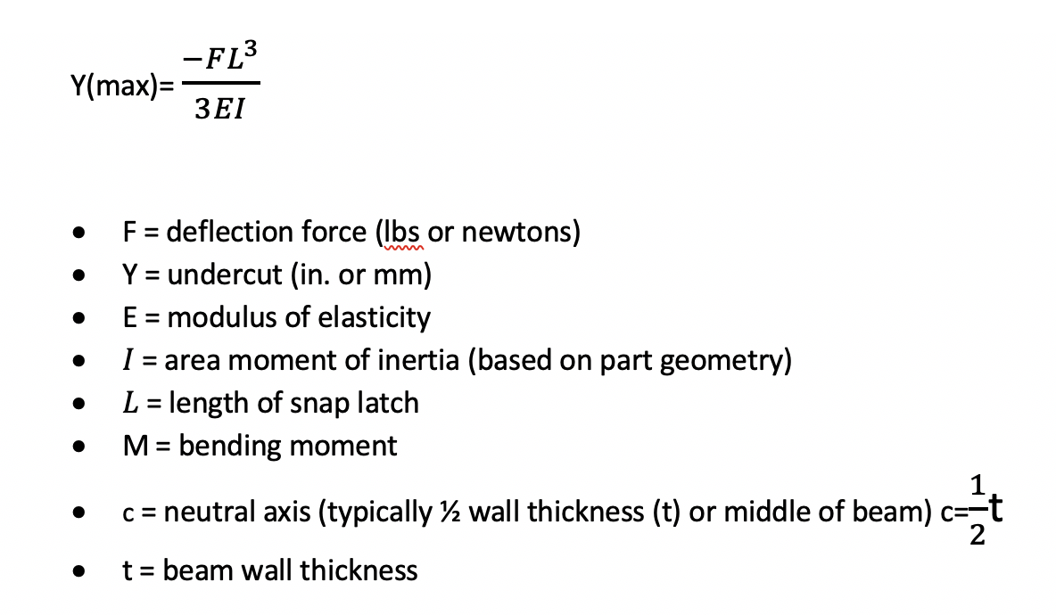
Since cantilever snap deflections should also be limited to flex within the elastic limit of a material, the induced stresses should be set to the maximum elastic limit of the material for single use or restricted to 50% of that level for repeated use where fatigue could cause premature failure. Determining the induced stress at the base of the snap can be calculated by:
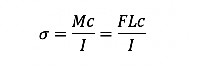
Or, the maximum allowable deflection within the material’s elastic limit can be calculated by substituting the force F with the equivalent maximum stress, as follows:

Examples of I (area moment of inertia) are shown below:
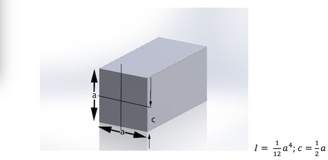
Figure 1.
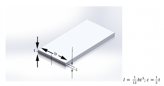
Figure 2.
It should be noted that the neutral axis c is only equal to one-half the snap beam wall thickness if the cross-sectional geometry of the beam is symmetrical about it. Since the snap beams may have a T- or U-beam cross section for added stiffness, the neutral axis must be computed based on the formulas given below for each respective cross section.
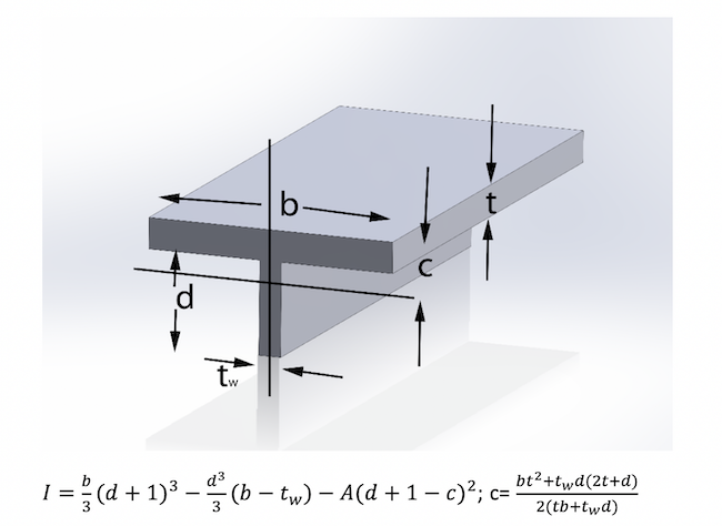
Figure 3.
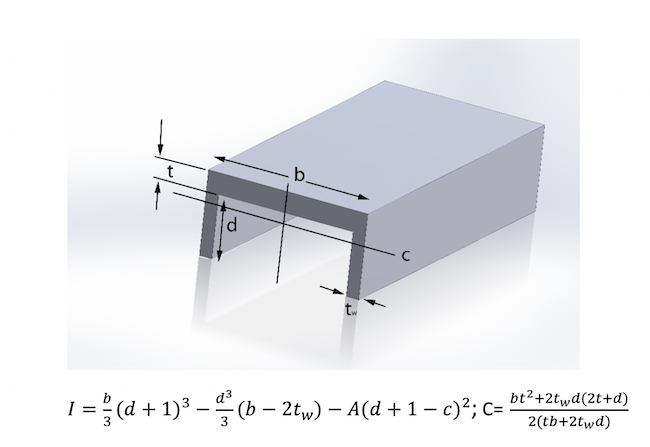
Figure 4.
Examples of snap designs with these various cross sections are shown below.
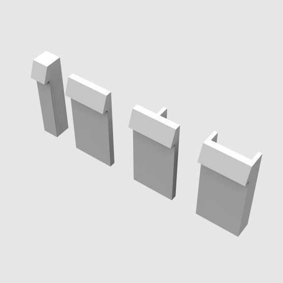
Figure 5.
It should be noted that these calculations are based on the following assumptions:
• The deflections are small, and the material strain is within the elastic region of the stress-strain curve.
• The cross-sectional area of the snap is constant. Typically, snap fingers are trapezoidal, and the cross section varies throughout the length of the beam.
• The base wall of the snap is rigid and will not deform. Typically, cantilevered snaps are attached to a plastic wall, which will also deform to some extent.
These calculations, therefore, should be considered estimated values. More-accurate predictions can be computed with FEA programs, which are built into many CAD programs. Although the calculation of area moment of inertia is simple for a square or rectangular cross section, it can get quite time consuming for other cross sections, as indicated by the more-complex equations. You can determine the area moment of inertia for any cross section simply by measuring the area properties in your 3D CAD program. I believe all 3D CAD programs offer this feature, which will accurately compute the area moment of inertia for shapes other than those discussed in this article.
An example of an FEA analysis of a simple cantilevered snap lock is shown below. The analysis was based on the following values:
Snap thickness = 0.090 in. (t)
Snap width = 0.6 in. (b)
Snap length to tip of hook = 1 in. (L)
Horizontal force applied at tip to deflect 0.06 in. = amount of undercut for hook = 2.0 lbs (F)
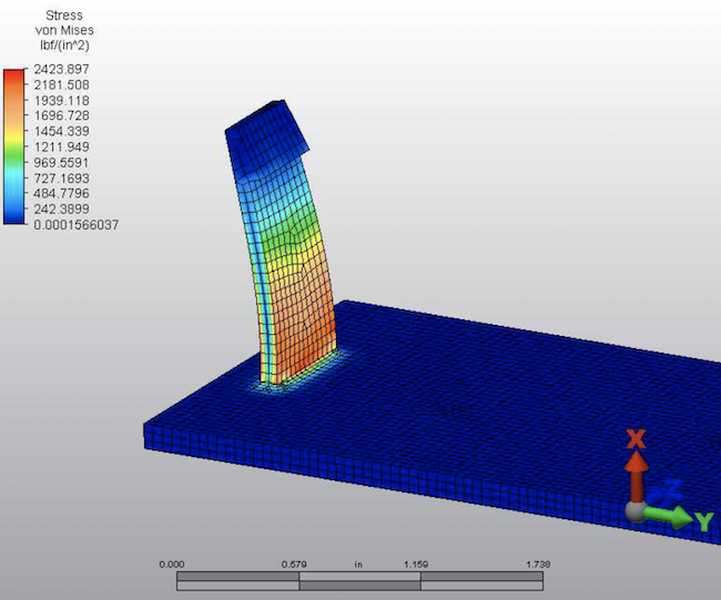
The maximum von Mises stress = 2423 psi at base. Using this equation,
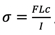
we can also compute the stresses and compare the results to the FEA study.

As previously stated, plastic snap locks should be designed to comply with several considerations as listed at the beginning of this article. We’ve covered the structural considerations; now we will review some other requirements.
Since all snaps are based on the deflection and interlocking of two parts, it’s important to remember that the force vectors applied for assembly will also be responsible for disassembly. If a snap is required to securely lock two parts together, you should restrict the six degrees of freedom between the two parts to only one required to release the snap. This simple but often overlooked consideration will prevent two parts from popping apart during a drop test or other stressful conditions. The illustration below more clearly communicates this point.
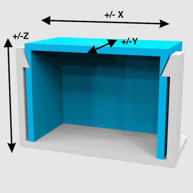
Figure 6.
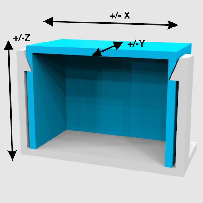
Figure 7.
The design in figure 6 illustrates an example of a snap assembly that can easily pop apart since the blue cover is only restrained in the +/- Z axis by the snap and floor of the mating part. Although the two parts are interlocked, the blue part can slide in both X and Y axes, inducing strain on the snap that could deflect enough to release the lower cover. Conversely, the assembly in figure 7 includes an inner lip restricting the blue cover from sliding in X or Y directions. The only loads that can be transferred to the snaps are now restricted to tensile and torsional loads, providing a much more secure interlock.
Snap locks are often used to assemble parts for repeated assembly and disassembly. It’s good design practice to limit the deflection of the snap, preventing it from being over stressed and permanently deformed. This can be done by simply adding a rib or barrier behind the snap, limiting its deflection within its elastic limit.
Ideally, snaps should be designed to return to an unstressed position after they engage with the mating part. However, snap locks can remain under constant stress in the engaged position, provided the stress is well below the maximum long-term working limit of the material, which is typically 50% of the elastic limit. If two parts are to be snapped together and pulled apart with a simple push-pull action, the hook profile should be designed as an isosceles triangular profile versus a right-angle profile. The isosceles profile will enable the force vector to deflect the snap in either direction equally. If the angles on either side of the hook are not equal, the forces will differ accordingly.
Two of the production design challenges that must be considered when designing a snap are tolerances and tool design. Secure snap engagements require tight fits and consistency in maintaining tolerances during production. Tolerance control is dependent on tool quality, production control and material. Material shrinkage rates will significantly affect tolerances. Typically, unfilled amorphic polymers tend to shrink isotropically and maintain better tolerances then semi-crystalline plastics, which shrink anisotropically. Glass-fiber reinforcement also affects shrinkage characteristics and tolerance control. It’s advisable to discuss tolerance requirements with your molder and toolmaker before releasing files for tooling. Some molders will request that the CAD files be adjusted by adding a few thousandths more clearance, which can easily be tightened after first samples are evaluated. This precaution is referred to as “steel safe,” which implies the extra steel in the mold can easily be removed versus the costly and time-consuming process of welding and machining.
The second production consideration pertaining to tool design is equally important. Snap features can be added to a part such that the hook features are in line of draw or require a sliding action in the mold. Ideally, snaps should be designed so the hook features remain in line of draw, keeping the mold simple and reliable. However, when this is not possible, you must consider how the slide will be actuated and verify there are no features in your design that would prevent the slide from moving. Snaps in line of draw must be drafted properly to allow the core and cavity to properly kiss off without galling the mold surface.
I hope this brief introduction to snap-fit design for injection molded parts has been informative and beneficial to you. Injection molding offers designers countless benefits in creating complex, highly functional parts that can be extremely attractive, cost effective and reliable. Understanding material properties and applying the basic formulas provided in this article to your imaginative concepts will enable you to optimize your designs.
Article source: Plastics today


